5 Common Cable Faults and How to Prevent Them
Time: 2025-08-07 15:26:50
Source: Henan Province Jianyun Cable Co., Ltd.
Electrical cables, used in low-voltage (0.6/1 kV) and medium-voltage (3.6/6 kV to 26/45 kV) power distribution, control, and communication systems, are susceptible to faults that can disrupt performance, cause outages, or pose safety risks. Identifying and preventing common cable faults is essential for ensuring reliability and extending cable lifespan, typically 25–30 years. This guide details five prevalent cable faults, their causes, and preventive measures, presented in a formal and structured manner.
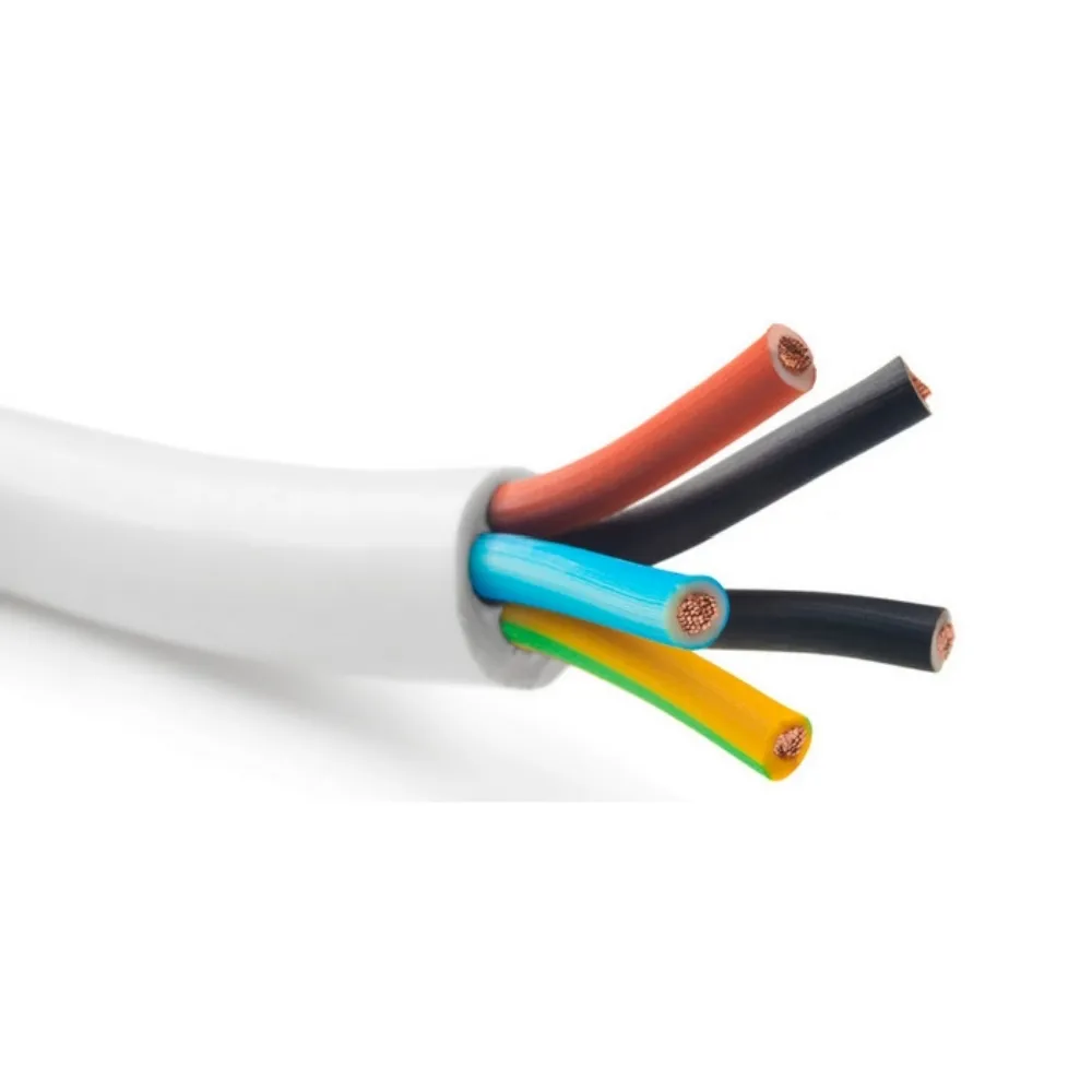
Table of Contents
1. Overview of Cable Faults
Cable faults occur due to defects in the conductor, insulation, or sheathing, often resulting from mechanical damage, environmental factors, or improper installation. These faults can lead to short circuits, open circuits, or signal degradation, impacting applications such as power distribution, industrial control, or telecommunications. Early detection and prevention, guided by standards like IEC 60502, are critical to maintaining system reliability and safety.
|
Fault Type
|
Impact
|
|
Short Circuit
|
Overcurrent, equipment damage
|
|
Open Circuit
|
Power or signal loss
|
|
Insulation Failure
|
Leakage, safety hazards
|
2. Common Cable Faults and Prevention
The following are five common cable faults, their causes, and preventive measures:
-
1. Insulation Breakdown:
-
Description: Degradation or puncture of insulation (e.g., XLPE, PVC) causes leakage currents or short circuits, often detected as low insulation resistance (<100 MΩ/km).
-
Causes: Overheating (exceeding 90°C for XLPE, 70°C for PVC), moisture ingress, or mechanical damage during installation.
-
Prevention:
-
Select cables with appropriate insulation for operating conditions (e.g., XLPE for high-temperature environments).
-
Apply derating factors for high ambient temperatures (e.g., 0.91 for XLPE at 40°C per IEC 60502).
-
Seal cable ends with caps during storage and installation to prevent moisture ingress.
-
Conduct insulation resistance tests (e.g., 3.5 kV AC for 0.6/1 kV cables) before commissioning.
-
2. Conductor Breakage (Open Circuit):
-
Description: A break in the conductor (copper or aluminum) interrupts current flow, causing power or signal loss.
-
Causes: Excessive bending (below minimum radius, e.g., 6–12 times cable diameter), tensile stress during pulling, or fatigue in dynamic applications.
-
Prevention:
-
Adhere to minimum bending radii during installation (e.g., 12D for armored cables).
-
Use pulling lubricants and proper equipment (e.g., cable rollers) to limit tensile stress (max 50 N/mm² for copper, 30 N/mm² for aluminum).
-
Choose stranded conductors (Class 2 or 5 per IEC 60228) for flexibility in dynamic applications.
-
Inspect cables visually and with continuity tests before installation.
-
3. Mechanical Damage:
-
Description: Physical damage to insulation, sheathing, or conductors from impact, crushing, or abrasion, leading to faults like short circuits.
-
Causes: Improper handling, heavy machinery in industrial settings, or inadequate protection in underground installations.
-
Prevention:
-
Use armored cables (e.g., steel wire armor, SWA) for underground or industrial applications.
-
Install cables in protective conduits or trays in high-risk areas.
-
Train personnel on proper handling and use equipment like forklifts for cable drums (e.g., 2-ton capacity for 1-ton drums).
-
Conduct post-installation visual inspections to identify cuts or abrasions.
-
4. Corrosion-Induced Faults:
-
Description: Corrosion of conductors (especially aluminum) or armor layers reduces conductivity or causes insulation failure.
-
Causes: Exposure to moisture, chemicals, or galvanic corrosion at copper-aluminum joints.
-
Prevention:
-
Use corrosion-resistant sheathing (e.g., PVC, PE) and galvanized steel for SWA.
-
Apply anti-oxidant compounds and bimetallic connectors for aluminum-copper terminations.
-
Store cables in dry, covered areas (e.g., -20°C to 40°C) to prevent moisture ingress.
-
Conduct periodic resistance tests to detect corrosion early.
-
5. Electromagnetic Interference (EMI)-Induced Faults:
-
Description: EMI from nearby power cables or equipment induces noise in control or communication cables, causing signal errors.
-
Causes: Proximity to high-current cables, motors, or RF sources; inadequate shielding.
-
Prevention:
-
Use shielded cables (e.g., copper braid, aluminum foil) for control or communication systems.
-
Maintain 150–300 mm separation between power and signal cables or use metallic dividers.
-
Ground shields properly (e.g., one end for high-frequency EMI, both ends for low-frequency).
-
Install EMI filters (e.g., ferrite cores) at cable entry points.
|
Fault
|
Causes
|
Prevention
|
|
Insulation Breakdown
|
Overheating, moisture
|
XLPE for high temps, seal ends
|
|
Conductor Breakage
|
Excessive bending, stress
|
Adhere to bending radii, use rollers
|
|
Mechanical Damage
|
Impact, crushing
|
Armored cables, conduits
|
|
Corrosion
|
Moisture, chemicals
|
Anti-oxidant, bimetallic connectors
|
|
EMI
|
Proximity to sources
|
Shielded cables, separation
|
3. Testing and Maintenance Practices
Regular testing and maintenance help detect and prevent cable faults:
-
Insulation Resistance Test: Measure resistance (e.g., >1000 MΩ/km for XLPE at 20°C) to detect insulation degradation.
-
Continuity Test: Verify conductor integrity to identify breaks or high-resistance points.
-
Time Domain Reflectometry (TDR): Locate faults by analyzing signal reflections in cables.
-
Visual Inspections: Check for physical damage, corrosion, or improper terminations during installation and maintenance.
-
Periodic Maintenance: Schedule annual inspections and tests, especially for underground or industrial cables, to ensure long-term reliability.
|
Test/Maintenance
|
Details
|
|
Insulation Resistance
|
>1000 MΩ/km for XLPE
|
|
Continuity
|
Detect conductor breaks
|
|
TDR
|
Locate faults
|
|
Visual Inspections
|
Check damage, corrosion
|
4. Standards and Compliance
Adhering to standards ensures fault prevention and safety:
-
IEC 60502-1 (LV): Specifies insulation and testing requirements for 0.6/1 kV cables.
-
IEC 60502-2 (MV): Covers MV cables (3.6/6 kV to 26/45 kV) with enhanced insulation and armor requirements.
-
IEC 60228: Defines conductor classes for reliable performance.
-
IEC 61000-5-2: Provides guidelines for EMI shielding and grounding.
-
Regional Standards: Comply with CCC (China), CE (Europe), or UL (North America) for project-specific requirements.
|
Standard
|
Details
|
|
IEC 60502-1
|
LV cable requirements
|
|
IEC 60502-2
|
MV cable requirements
|
|
IEC 60228
|
Conductor classes
|
|
IEC 61000-5-2
|
EMI shielding, grounding
|
5. Challenges and Solutions
|
Challenge
|
Solution
|
|
Cost of Prevention
|
Use unarmored cables in low-risk areas, prioritize critical systems
|
|
Installation Errors
|
Train personnel, follow bending and pulling guidelines
|
|
Environmental Exposure
|
Use armored cables, corrosion-resistant sheathing
|
|
Detecting Hidden Faults
|
Implement TDR, regular testing
|
6. Conclusion
Preventing common cable faults—insulation breakdown, conductor breakage, mechanical damage, corrosion, and EMI—requires careful selection, proper installation, and regular maintenance. By using appropriate cables (e.g., XLPE for high temperatures, armored for mechanical protection), adhering to installation guidelines (e.g., bending radii, segregation), and conducting tests like insulation resistance and TDR, users can ensure reliable performance in power distribution, industrial, or communication systems. Compliance with standards like IEC 60502 and proactive maintenance strategies minimize downtime and safety risks, supporting a cable lifespan of 25–30 years.


