Time: 2025-08-26 14:39:19 Source: Henan Province Jianyun Cable Co., Ltd.
Effective DC cable routing in solar photovoltaic (PV) power projects is critical for ensuring system efficiency, safety, and longevity, typically designed for a lifespan of 25–30 years. DC cables, used to connect solar panels to inverters and combiner boxes, operate at voltages up to 1.8/3 kV DC and must withstand environmental challenges, minimize energy losses, and comply with standards like EN 50618 and IEC 62930. Proper routing reduces risks such as insulation breakdown, overheating, and electromagnetic interference (EMI), particularly in rooftop and ground-mounted solar installations. This guide outlines best practices for DC cable routing in solar power projects, presented in a formal and structured manner.
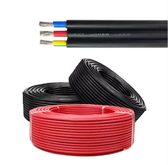
DC cables in solar PV systems transmit direct current from solar panels to combiner boxes, inverters, or battery storage systems, typically at voltages of 600–1500 V DC. These cables, often single-core with XLPE or EPR insulation, are exposed to environmental stressors like UV radiation, temperature extremes, and mechanical strain. Proper routing ensures minimal voltage drop (<1.5% per EN 50618), protects insulation integrity, and prevents faults like short circuits or EMI-induced signal issues. Effective routing also simplifies maintenance and ensures compliance with safety and performance standards.
| Aspect | Details |
|---|---|
| Purpose | Transmit DC from panels to inverters |
| Voltage Range | 600–1500 V DC |
| Insulation | XLPE, EPR |
| Standards | EN 50618, IEC 62930 |
Implementing best practices for DC cable routing enhances system performance and durability. The following guidelines address environmental, electrical, and mechanical considerations:
| Best Practice | Details | Example |
|---|---|---|
| Minimize Length | Reduce VD <1.5% | 4 mm² for 15 A, 20 m |
| Conduits/Trays | UV-resistant, sealed | Schedule 80 PVC |
| Bending Radii | 4–6 times diameter | >24 mm for 6 mm cable |
| Segregation | 150–300 mm separation | Separate DC/AC trays |
| Secure Cables | UV-resistant ties | Nylon 66 ties |
| Connectors | Weatherproof, IP67 | MC4 connectors |
| Thermal Expansion | Slack, expansion loops | 1–2 cm per 10 m |
Adhering to standards ensures safe and reliable DC cable routing:
| Standard | Details |
|---|---|
| EN 50618 | UV resistance, 1.5 kV DC |
| IEC 62930 | 1.8/3 kV DC, PD testing |
| IEC 60332-1 | Flame-retardant properties |
| IEC 60228 | Conductor classes |
Regular maintenance ensures long-term reliability of DC cable routing:
| Maintenance Task | Details |
|---|---|
| Visual Inspections | Check UV damage, abrasion |
| Insulation Resistance | >1000 MΩ/km |
| Thermal Imaging | Detect hotspots |
| Connector Checks | Verify IP67 sealing |
| Challenge | Solution |
|---|---|
| UV and Weather Exposure | Use UV-resistant conduits, XLPO cables |
| EMI Interference | Maintain DC/AC separation, use shielded cables |
| Overheating | Size conductors, apply derating (e.g., 0.91 at 40°C) |
| Installation Errors | Train installers, follow bending radii |
Effective DC cable routing in solar power projects is essential for minimizing energy losses, ensuring safety, and achieving a system lifespan of 25–30 years. Best practices include minimizing cable length, using protective conduits, maintaining bending radii, segregating DC and AC cables, securing cables, using proper connectors, and accounting for thermal expansion. Compliance with standards like EN 50618 and IEC 62930, along with regular maintenance (e.g., insulation tests, thermal imaging), ensures reliable performance. By addressing challenges like UV exposure and EMI through strategic routing and cable selection, solar PV systems can operate efficiently in rooftop and ground-mounted applications.
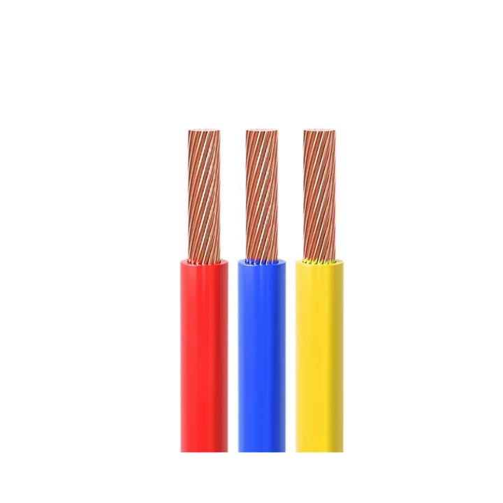
CE Certification 450/750v H07VVF Flexible Copper PVC Insulated Ac Cable 3*2.5 Mm
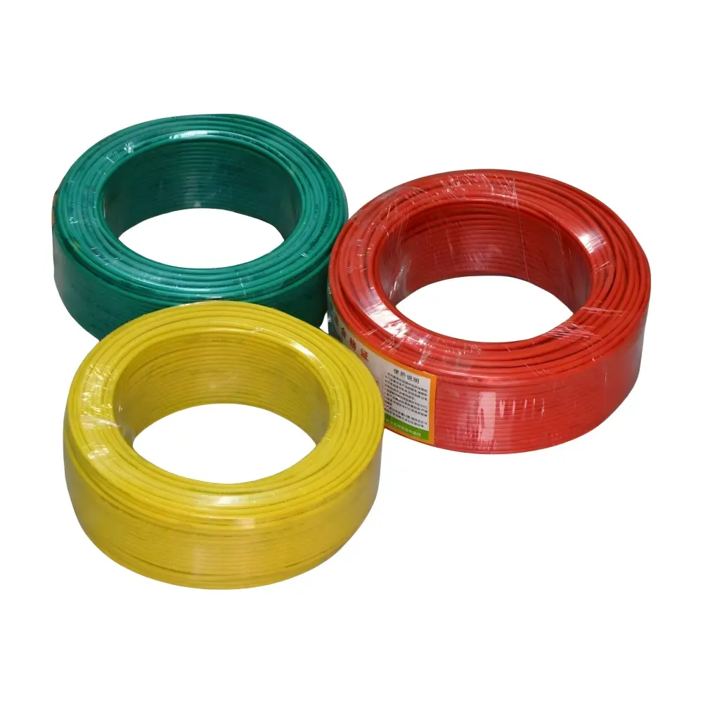
low voltage copper conductor PVC insulation underground BV BVR cable for industr
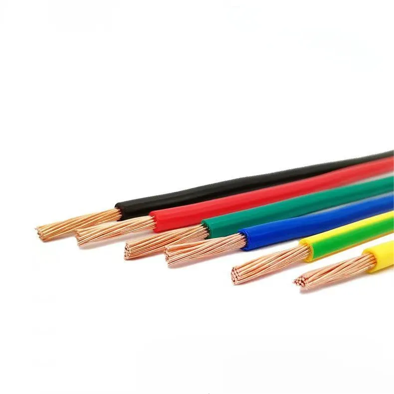
PVC electric wires are one of the most widely used electrical conductors in resi
H07V-U wire is a flexible, low voltage electrical wire commonly used in industri