
Keep up to date with our latest company news and relevant industry knowledge.
Time: 2025-06-12 15:01:33 Source: Henan Province Jianyun Cable Co., Ltd.
Proper cable sizing is essential for ensuring the safety, efficiency, and longevity of electrical systems in industrial installations. Industrial environments demand cables that can handle high power loads, long distances, and harsh conditions while complying with regulatory standards. This guide outlines the key factors, processes, and practical considerations for selecting the correct cable size, providing a structured approach to meet the unique demands of industrial applications.
Several factors influence cable sizing in industrial installations, each critical to ensuring system performance and safety.
The current-carrying capacity (ampacity) of a cable is the maximum current it can safely conduct without exceeding its temperature rating. This depends on the conductor material (e.g., copper or aluminum), insulation type, and installation conditions. Overloading a cable beyond its ampacity can cause overheating, insulation degradation, or fire hazards.
Voltage drop occurs due to the resistance of the cable over its length, reducing the voltage delivered to the load. Excessive voltage drop can impair equipment performance, particularly for motors or sensitive electronics. Industrial standards typically limit voltage drop to 3-5% for power circuits.
Cables must withstand the thermal and mechanical stresses of short-circuit currents without damage. The short-circuit rating depends on the conductor size, material, and fault duration, ensuring the cable can handle fault conditions until protective devices (e.g., circuit breakers) operate.
Industrial environments often expose cables to extreme temperatures, moisture, UV radiation, chemicals, or mechanical stress. These conditions require cables with appropriate insulation, jacketing, and armoring (if needed). Installation methods, such as direct burial, conduit, or cable tray, also affect sizing due to heat dissipation and derating factors.
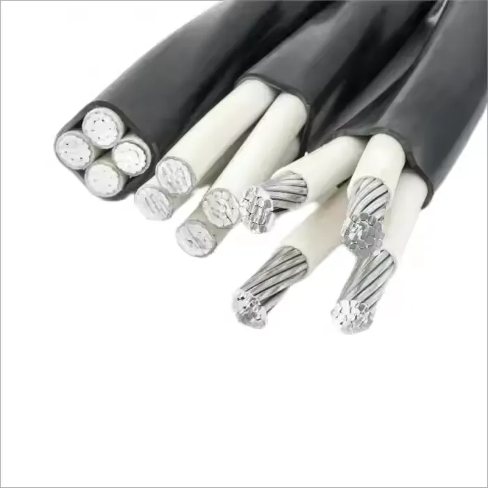
The choice of cable type—armored or unarmored, single-core or multi-core, copper or aluminum—affects sizing. Armored cables, such as Steel Wire Armored (SWA) or Metal-Clad (MC), are preferred for outdoor or harsh industrial settings due to their durability, while unarmored cables may suffice in protected environments.
The cable sizing process involves a systematic approach to ensure all factors are addressed. The following steps provide a structured methodology.
Identify the load characteristics, including:
Account for future expansion or diversity factors to avoid undersizing.
Calculate the full load current (I) using the appropriate formula based on the system type:
Apply a safety margin (e.g., 125% of the calculated current) to account for inrush currents or overloads.
Derating adjusts the cable’s ampacity based on environmental and installation conditions, such as:
Derated ampacity = Base ampacity × Correction factor(s).
Calculate voltage drop to ensure it remains within acceptable limits (e.g., 3-5%):
If the voltage drop exceeds limits, increase the conductor size or adjust the installation method.
Ensure the cable can withstand short-circuit currents using:
Compare the calculated I_sc to the system’s prospective fault current to confirm adequacy.
Choose the smallest conductor size that meets:
Refer to manufacturer tables or standards for conductor sizes (e.g., mm² or AWG).
The choice of cable type impacts sizing due to differences in construction and application:
Beyond calculations, consider the following:
Scenario: A three-phase motor with a 100 kW load operates at 400 V, with a power factor of 0.85, over a 150 m cable run in an outdoor industrial setting (ambient temperature 40°C, installed in a cable tray).
Adhere to relevant standards, such as:
Local codes may specify additional requirements, such as conduit use or specific cable types. Always consult a professional to ensure compliance.
Proper cable sizing for industrial installations requires careful consideration of current-carrying capacity, voltage drop, short-circuit ratings, environmental conditions, and cable type. By following a structured sizing process and accounting for practical and regulatory factors, engineers can ensure safe, efficient, and reliable electrical systems. Armored cables, such as SWA or MC, are often the best choice for industrial settings due to their durability and suitability for harsh conditions. Professional consultation is recommended to validate selections and ensure compliance with standards.

CE Certification 450/750v H07VVF Flexible Copper PVC Insulated Ac Cable 3*2.5 Mm

low voltage copper conductor PVC insulation underground BV BVR cable for industr

PVC electric wires are one of the most widely used electrical conductors in resi

H07V-U wire is a flexible, low voltage electrical wire commonly used in industri


