Case Study: Cable System Design for a Wind Energy Farm
Time: 2025-07-22 16:31:54
Source: Henan Province Jianyun Cable Co., Ltd.
This case study examines the cable system design for a hypothetical 100 MW offshore wind energy farm located 20 km off the coast, comprising 20 wind turbines, each with a capacity of 5 MW. The project requires a robust cabling system to transmit power from turbines to an onshore substation, integrate with monitoring systems, and withstand harsh marine and environmental conditions. The design prioritizes efficiency, safety, and compliance with international standards, addressing challenges such as saltwater corrosion, mechanical stress, and high-voltage transmission. This document outlines the design process, cable selections, implementation strategy, and outcomes, presented in a formal and structured manner.
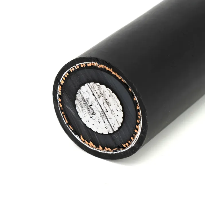
Table of Contents
1. Project Overview and Requirements
The wind energy farm consists of 20 offshore wind turbines, each generating 5 MW at 6.6 kV, connected via inter-array cables to an offshore substation. The substation steps up the voltage to 33 kV for transmission to an onshore substation via an export cable. The project requires:
-
Power Transmission: Efficient delivery of 100 MW from turbines to the onshore grid with minimal losses.
-
Data Communication: Real-time monitoring and control of turbines using SCADA systems, requiring high-speed data transmission.
-
Environmental Resilience: Cables must withstand saltwater corrosion, UV radiation, temperatures from -20°C to 60°C, and mechanical stress from waves and seabed conditions.
-
Safety and Compliance: Adherence to standards such as IEC 60502, IEC 60092, DNV-GL, and ATEX/IECEx for hazardous areas (e.g., Zone 2 for gas risks).
-
Scalability: Design to accommodate potential expansion to 150 MW with additional turbines.
2. Design Challenges
The offshore wind farm presents several challenges for the cabling system design:
-
Marine Environment: Saltwater exposure and seabed abrasion require corrosion-resistant and mechanically robust cables.
-
Long-Distance Transmission: The 20 km export cable must minimize power losses while maintaining cost-effectiveness.
-
Dynamic Conditions: Inter-array cables must handle dynamic stresses from tidal movements and wave action.
-
Fire Safety: Cables in confined substation areas must be low-smoke, zero-halogen (LSZH) to ensure safety during fire incidents.
-
Installation Complexity: Subsea cable laying requires specialized vessels and precise routing to avoid damage and ensure stability.
-
Regulatory Compliance: Compliance with marine and electrical standards, including DNV-GL, IEC 60092, and local grid codes.
3. Cable System Design
The cable system is divided into three main components: inter-array cables, export cables, and communication cables, integrated with the wind farm’s electrical and monitoring systems.
-
Inter-Array Cables: Connect turbines in a string configuration to the offshore substation, transmitting 6.6 kV AC power. Each string connects five turbines, with four strings total.
-
Export Cable: Transmits 33 kV AC power from the offshore substation to the onshore substation over 20 km, designed for high efficiency and durability.
-
Communication Cables: Fiber optic cables for SCADA systems, enabling real-time monitoring of turbine performance, environmental conditions, and grid integration.
-
System Integration: Cables interface with transformers, switchgear, and SCADA systems, with provisions for future expansion to 150 MW.
4. Cable Specifications and Selection
The following cable types were selected based on the project’s technical and environmental requirements:
4.1 Inter-Array Cables
-
Type: Medium-Voltage Marine-Grade Cables (6.6 kV).
-
Construction: Tinned copper conductors, XLPE insulation, water-blocking tape, steel wire armoring (SWA), and LSZH sheathing.
-
Specifications:
-
Conductor: 95 mm² tinned copper for low resistance.
-
Insulation: XLPE for high dielectric strength.
-
Sheathing: LSZH for fire safety, UV and saltwater resistance.
-
Armoring: SWA for mechanical protection against seabed abrasion.
-
Temperature Range: -20°C to 90°C.
-
Applications: Connecting turbines to the offshore substation.
-
Standards: IEC 60502-2, IEC 60092-353, DNV-GL.
4.2 Export Cable
-
Type: Medium-Voltage Submarine Cable (33 kV).
-
Construction: Aluminum conductors, XLPE insulation, lead sheath for water impermeability, double steel wire armoring, and PE outer sheath.
-
Specifications:
-
Conductor: 400 mm² aluminum for cost-effective high-current capacity.
-
Insulation: XLPE for low dielectric losses.
-
Sheathing: PE with anti-corrosion coating, water-blocking layers.
-
Armoring: Double SWA for enhanced mechanical strength.
-
Temperature Range: -20°C to 80°C.
-
Applications: Transmitting power from the offshore substation to the onshore grid.
-
Standards: IEC 60502-2, IEC 60840, DNV-GL.
4.3 Fiber Optic Communication Cables
-
Type: Single-Mode Fiber Optic Cables.
-
Construction: Single-mode fibers, LSZH sheathing, water-blocking gel, and steel wire armoring for subsea use.
-
Specifications:
-
Fiber Count: 24 fibers for high-bandwidth SCADA communication.
-
Sheathing: LSZH for fire safety, UV and saltwater resistance.
-
Armoring: SWA for mechanical protection.
-
Temperature Range: -20°C to 70°C.
-
Applications: Real-time monitoring and control of turbines and substation systems.
-
Standards: IEC 60794, ITU-T G.652, IEC 60092-370.
4.4 Fire-Resistant Cables
-
Type: Low-Voltage Fire-Resistant Cables (0.6/1kV).
-
Construction: Copper conductors, mica tape insulation, LSZH sheathing, and optional SWA armoring.
-
Specifications:
-
Conductor: 16–50 mm² copper for control circuits.
-
Insulation: Mica tape for fire resistance, XLPE for durability.
-
Sheathing: LSZH for low smoke and toxicity.
-
Temperature Range: -20°C to 90°C.
-
Applications: Emergency systems in the offshore substation, including alarms and shutdown circuits.
-
Standards: IEC 60331, BS 6387, EN 50575.
5. Implementation and Installation
The cable system implementation involved the following steps:
-
Site Survey: Conducted a seabed survey to identify optimal cable routes, avoiding rocky areas and ensuring stable burial depth (1–2 m).
-
Cable Laying: Utilized a cable-laying vessel with dynamic positioning to install inter-array and export cables, using trenching and jetting techniques for burial.
-
Cable Protection: Applied rock dumping and concrete mattresses in high-risk areas to protect cables from anchor damage or tidal currents.
-
Connections: Used marine-grade, IP68-rated cable joints and terminations, with ATEX-certified glands for hazardous areas in the substation.
-
Grounding: Implemented equipotential bonding for armored cables and substation equipment to prevent static buildup, per IEC 60079-14.
-
Testing: Conducted pre-installation and post-installation tests, including insulation resistance (5000 V DC), continuity, and OTDR (Optical Time-Domain Reflectometer) tests for fiber optic cables.
-
Commissioning: Integrated cables with turbines, switchgear, and SCADA systems, verifying performance under full load conditions.
6. Maintenance and Monitoring
Ongoing maintenance ensures long-term reliability and compliance:
-
Periodic Inspections: Annual visual and ROV (Remotely Operated Vehicle) inspections of subsea cables to check for abrasion or exposure, per IEC 60079-17.
-
Electrical Testing: Biannual insulation resistance and partial discharge tests to detect degradation, using megohmmeters and PD analyzers.
-
Fiber Optic Monitoring: Continuous monitoring of fiber optic cables using SCADA systems to ensure data integrity and detect faults.
-
Maintenance Records: Detailed logs of inspections, tests, and repairs maintained for regulatory compliance and troubleshooting.
-
Environmental Monitoring: Regular checks for corrosion or marine growth on cables, with cleaning or repairs as needed.
7. Outcomes and Lessons Learned
The cable system design and implementation yielded the following outcomes:
-
Efficiency: Power losses were limited to 2% across the 20 km export cable, achieved through optimized conductor sizing and XLPE insulation.
-
Reliability: No cable failures reported in the first year of operation, attributed to robust armoring and corrosion-resistant materials.
-
Safety: LSZH and fire-resistant cables ensured compliance with fire safety standards, enhancing safety in the offshore substation.
-
Scalability: The design accommodated a planned expansion to 150 MW by reserving capacity in the offshore substation and export cable.
-
Lessons Learned:
-
Early seabed surveys were critical to avoid costly rerouting during installation.
-
Pre-shipment testing of cables prevented delays by identifying manufacturing defects.
-
Collaboration with certified marine contractors ensured compliance with DNV-GL standards.
8. Conclusion
The cable system design for the 100 MW offshore wind energy farm successfully addressed the challenges of power transmission, data communication, and environmental resilience. By selecting marine-grade medium-voltage cables, submarine export cables, fiber optic cables, and fire-resistant cables, the project achieved high efficiency, safety, and compliance with standards like IEC 60502, IEC 60092, and DNV-GL. Proper installation, using specialized vessels and ATEX-certified components, and ongoing maintenance ensured long-term reliability. This case study demonstrates the importance of tailored cable selection, rigorous testing, and strategic planning in delivering robust cabling systems for offshore wind farms, with scalability for future expansions.


