How to Calculate Cable Size for Solar Panel Installations
Time: 2025-07-31 08:10:29
Source: Henan Province Jianyun Cable Co., Ltd.
Calculating the appropriate cable size for solar panel installations is essential to ensure safety, efficiency, and reliability in photovoltaic (PV) systems. Properly sized cables minimize power losses, prevent overheating, and comply with regulatory requirements. This guide provides a structured, step-by-step approach to calculating the correct cable size for DC solar PV systems, focusing on electrical parameters, environmental considerations, and practical applications, presented in a formal and professional manner.
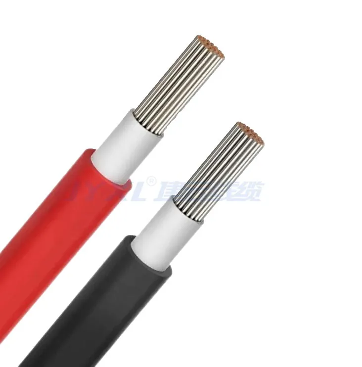
Table of Contents
1. Overview of Solar PV Cables
Solar PV cables are single-core, insulated cables designed for DC applications in PV systems, connecting solar panels to inverters, charge controllers, or combiner boxes. Typically made with tinned copper conductors for corrosion resistance and cross-linked polyethylene (XLPE) insulation for UV and temperature resistance, these cables handle voltages up to 1.0–1.5 kV DC. Common sizes range from 1.5 mm² to 16 mm², and proper sizing ensures minimal voltage drop, safe current-carrying capacity, and a system lifespan of 25–30 years.
2. Key Factors in Cable Sizing
Calculating the correct cable size requires consideration of several factors:
-
Current-Carrying Capacity (Ampacity): The cable must handle the maximum current (Imp or Isc) from the PV modules without exceeding its temperature rating (typically 90°C).
-
Voltage Drop: Voltage drop should be limited to 1–3% to maintain system efficiency, particularly over long cable runs.
-
Cable Length: Longer runs increase resistance, requiring larger cable sizes to minimize losses.
-
System Voltage: Cables must be rated for the system’s maximum DC voltage (e.g., 600 V to 1.5 kV DC).
-
Environmental Conditions: Temperature, UV exposure, and moisture affect cable performance, requiring derating for high temperatures or harsh conditions.
-
Future Expansion: Larger cables accommodate increased current for potential system upgrades.
|
Factor
|
Consideration
|
|
Ampacity
|
Handle max current at 90°C
|
|
Voltage Drop
|
1–3% max
|
|
Cable Length
|
Larger size for longer runs
|
|
Environmental Conditions
|
Derate for high temperatures
|
3. Step-by-Step Calculation Process
Follow these steps to calculate the appropriate cable size for a solar PV system:
-
Determine Maximum Current:
-
Obtain the short-circuit current (Isc) or maximum power current (Imp) from the PV module datasheet. For example, a 300 W panel at 40 V produces Imp ≈ 7.5 A.
-
For parallel configurations, multiply Isc or Imp by the number of strings. Example: 2 strings of 7.5 A panels yield 15 A total.
-
Apply a safety factor (e.g., 1.25) to account for overcurrent conditions: 15 A × 1.25 = 18.75 A.
-
Assess Cable Length:
-
Measure the one-way distance (L) from the PV array to the inverter or combiner box. For DC cables, consider both positive and negative conductors (total length = 2 × L).
-
Example: A 10 m run requires accounting for 20 m total cable length (positive + negative).
-
Calculate Voltage Drop:
-
Use the formula: VD = (2 × I × L × R) / V × 100, where VD is voltage drop (%), I is current (A), L is cable length (m), R is resistance (Ω/km), and V is system voltage (V).
-
Typical resistance values for tinned copper (20°C): 1.5 mm² ≈ 12.1 Ω/km, 4 mm² ≈ 4.61 Ω/km, 6 mm² ≈ 3.08 Ω/km, 10 mm² ≈ 1.83 Ω/km, 16 mm² ≈ 1.15 Ω/km.
-
Example: For 18.75 A over 20 m (40 m total) on a 48 V system with 4 mm² cable: VD = (2 × 18.75 × 20 × 4.61) / 48 × 100 ≈ 7.2%. Since VD >3%, try 6 mm²: VD = (2 × 18.75 × 20 × 3.08) / 48 × 100 ≈ 4.8%. Use 10 mm² for VD ≈ 2.9%.
-
Check Ampacity:
-
Ensure the cable’s ampacity exceeds the calculated current with the safety factor. Typical ampacities (90°C): 4 mm² ≈ 40 A, 6 mm² ≈ 50 A, 10 mm² ≈ 70 A, 16 mm² ≈ 90 A.
-
Example: For 18.75 A, a 4 mm² cable (40 A) is sufficient.
-
Apply Derating for Environmental Conditions:
-
Derate ampacity for high ambient temperatures (e.g., >30°C). For 40°C, apply a derating factor of ~0.91: 40 A × 0.91 = 36.4 A for 4 mm².
-
If derated ampacity falls below the required current, select a larger size (e.g., 6 mm²).
-
Verify Voltage Rating:
-
Ensure the cable is rated for the system’s maximum DC voltage (e.g., 1.0 kV or 1.5 kV DC), as specified by the inverter or PV array.
-
Consider Future Expansion:
-
Select a larger cable size (e.g., 6 mm² instead of 4 mm²) to accommodate additional panels or higher currents in the future.
|
Step
|
Key Actions
|
|
Maximum Current
|
Calculate Isc/Imp, apply 1.25 safety factor
|
|
Cable Length
|
Measure total length (positive + negative)
|
|
Voltage Drop
|
Ensure <3% using VD formula
|
|
Ampacity
|
Check against derated capacity
|
4. Common Cable Sizes and Applications
Common DC PV cable sizes and their typical applications include:
-
1.5 mm²: Small systems (<500 W, <15 A), short runs (<5 m), e.g., off-grid setups or RVs. Ampacity: ~20 A.
-
4 mm²: Residential systems (1–5 kW, up to 40 A), runs <10 m. Ampacity: ~40 A, voltage: 1.0–1.5 kV DC.
-
6 mm²: Medium to large systems (5–10 kW, up to 50 A), runs of 10–20 m. Ampacity: ~50 A.
-
10 mm²: Commercial systems (10–50 kW, up to 70 A), longer runs. Ampacity: ~70 A.
-
16 mm²: Large commercial/industrial systems (>50 kW, up to 90 A), runs >20 m. Ampacity: ~90 A.
|
Cable Size (mm²)
|
Ampacity (A)
|
Application
|
Cable Run
|
|
1.5
|
~20
|
Small systems (<500 W)
|
<5 m
|
|
4
|
~40
|
Residential (1–5 kW)
|
<10 m
|
|
6
|
~50
|
Medium/large systems (5–10 kW)
|
10–20 m
|
|
10
|
~70
|
Commercial (10–50 kW)
|
10–20 m
|
|
16
|
~90
|
Industrial (>50 kW)
|
>20 m
|
5. Practical Considerations
Additional factors to ensure accurate cable sizing include:
-
Environmental Derating: Apply derating factors for ambient temperatures above 30°C or bundled cables to avoid overheating.
-
Connector Compatibility: Use connectors (e.g., MC4) rated for the cable’s voltage and current, ensuring proper sealing for outdoor use.
-
Installation Practices: Avoid sharp bends (minimum bend radius: 4–6 times cable diameter) and ensure proper cable management to prevent mechanical damage.
-
Cost vs. Efficiency: Larger cables reduce losses but increase costs; optimize size using tools like PVsyst or voltage drop calculators.
-
Future-Proofing: Select cables with a margin for additional panels to avoid costly replacements during system expansion.
6. Challenges and Solutions
|
Challenge
|
Solution
|
|
Excessive Voltage Drop
|
Use larger cables (e.g., 6 mm² or 10 mm²), shorten runs
|
|
Overheating
|
Select cables with sufficient ampacity, apply derating
|
|
Environmental Degradation
|
Choose UV-resistant, XLPE-insulated cables
|
|
Cost Constraints
|
Optimize size for efficiency, balance with material costs
|
7. Conclusion
Calculating the correct cable size for solar panel installations involves determining the maximum current, assessing cable length, calculating voltage drop, checking ampacity, and applying environmental derating. By selecting cables (e.g., 4 mm² for residential, 10–16 mm² for commercial) that meet system voltage and current requirements while keeping voltage drop below 3%, installers can ensure efficient and safe PV systems. Accounting for environmental conditions and future expansion further enhances system reliability, minimizing losses and ensuring a lifespan of 25–30 years.


