+86 13938808058 sales@jianyuncable.com
Blog
Blog

Keep up to date with our latest company news and relevant industry knowledge.

Home / Blog >How to Select the Right Size ACSR Conductor for Transmission Lines

How to Select the Right Size ACSR Conductor for Transmission Lines

Time: 2025-07-30 14:51:56 Source: Henan Province Jianyun Cable Co., Ltd.


Aluminum Conductor Steel Reinforced (ACSR) conductors are widely used in overhead transmission lines due to their high tensile strength, good conductivity, and cost-effectiveness. Selecting the appropriate ACSR conductor size is critical to ensure efficient power transmission, minimal losses, and structural integrity under environmental and electrical loads. This guide provides a structured approach to selecting the right ACSR conductor size for transmission lines, covering key considerations, calculations, and compliance with standards, presented in a formal and structured manner.

Table of Contents

1. Overview of ACSR Conductors

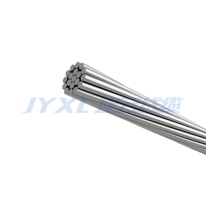
ACSR conductors consist of a steel core surrounded by aluminum strands, combining high conductivity (aluminum, 61% IACS) with mechanical strength (steel). They are used in low, medium, and high-voltage transmission lines, with configurations like 6/1 (6 aluminum strands, 1 steel wire) or 26/7, designated by names (e.g., Drake, Sparrow) per standards such as IEC 61089, ASTM B232, and BS EN 50182. Proper sizing ensures efficient power delivery, structural stability, and compliance with regulatory requirements.

2. Key Factors in Conductor Size Selection

Selecting the right ACSR conductor size involves evaluating electrical, mechanical, and environmental factors:

  • Current-Carrying Capacity (Ampacity): The conductor must handle the maximum current load without exceeding its temperature rating (typically 75–90°C, per IEC 60287).
  • Voltage Drop: Ensure voltage drop remains below acceptable limits (e.g., 3–5% for transmission lines) over the line length, based on conductor resistance.
  • Mechanical Strength: The conductor must withstand tensile forces from wind, ice, and its own weight, supporting spans of 500–1000 m or more.
  • Environmental Conditions: Consider temperature extremes, wind loads, and corrosion risks (e.g., coastal areas requiring galvanized or greased steel cores).
  • Line Length and Span: Longer lines or spans require larger conductors to minimize sag and ensure mechanical stability.
  • Cost Considerations: Balance conductor size with material and installation costs, as larger conductors increase expenses but reduce losses.
  • Regulatory Standards: Compliance with IEC 61089, ASTM B232, or local grid codes is mandatory.
Factor Consideration
Ampacity Handle max current at 75–90°C
Voltage Drop <3–5% over line length
Mechanical Strength Support wind, ice, and span loads
Environmental Conditions Temperature, corrosion resistance

3. Step-by-Step Selection Process

Follow these steps to select the appropriate ACSR conductor size:

  1. Determine Electrical Load:
    • Calculate the maximum current (I) using the power formula: P = √3 × V × I × cosφ (for three-phase systems), where P is power (W), V is line voltage (V), and cosφ is the power factor (typically 0.9).
    • Refer to ampacity tables (e.g., IEC 60287, ASTM B232) to select a conductor with sufficient current-carrying capacity at the operating temperature (e.g., 75°C).
  2. Calculate Voltage Drop:
    • Use the formula: VD = (I × L × R) / V × 100, where VD is voltage drop (%), I is current (A), L is line length (km), R is conductor resistance (Ω/km), and V is line voltage (V).
    • Ensure VD <3–5%. Increase conductor size if voltage drop exceeds limits.
  3. Assess Mechanical Requirements:
    • Calculate tensile strength needs based on span length, wind load (e.g., 100 km/h), and ice load (e.g., 5 mm radial ice, per IEC 60826).
    • Select a conductor with a steel core ratio (e.g., 7–20% steel) to meet strength requirements, using manufacturer data or standards like ASTM B232.
  4. Evaluate Environmental Conditions:
    • For high temperatures, select conductors with low sag (e.g., high steel content).
    • In corrosive environments (e.g., coastal areas), choose ACSR with heavy galvanization or grease coating.
  5. Check Sag and Tension:
    • Use sag-tension calculations (e.g., via software like PLS-CADD) to ensure clearance requirements (e.g., 5.5 m above roads per IEC 60364) under maximum temperature and load conditions.
    • Larger conductors or higher steel content reduce sag but increase weight and cost.
  6. Verify Standards Compliance:
    • Ensure the conductor meets IEC 61089, ASTM B232, or BS EN 50182 for electrical and mechanical properties.
    • Obtain certificates of conformance from manufacturers.
  7. Optimize Cost and Efficiency:
    • Balance conductor size with cost, considering material, installation, and power loss expenses over the line’s lifespan (25–40 years).
    • Use economic conductor sizing methods (e.g., Kelvin’s law) to minimize total costs.
Step Key Actions
Electrical Load Calculate current, refer to ampacity tables
Voltage Drop Ensure <3–5% using VD formula
Mechanical Strength Assess span, wind, and ice loads
Sag and Tension Use software for clearance calculations

4. Common ACSR Conductor Sizes

ACSR conductors are available in various sizes, designated by code names (e.g., Drake, Raven) or cross-sectional areas. Common sizes and their typical applications include:

  • Raven (33.6 mm² aluminum, 6/1): Used for low-voltage distribution, short spans (100–200 m), and rural networks.
  • Drake (403 mm² aluminum, 26/7): Suitable for medium to high-voltage transmission, long spans (500–800 m), and urban grids.
  • Cardinal (483 mm² aluminum, 54/7): Used for high-voltage transmission (69–220 kV), supporting large loads and long distances.
  • Pheasant (645 mm² aluminum, 54/19): Designed for extra-high voltage (EHV, >220 kV) lines with heavy loads and spans up to 1000 m.
Conductor Name Aluminum Area (mm²) Configuration Typical Application
Raven 33.6 6/1 Low-voltage distribution, short spans
Drake 403 26/7 Medium/high-voltage, long spans
Cardinal 483 54/7 High-voltage transmission
Pheasant 645 54/19 EHV, heavy loads

5. Standards and Compliance

ACSR conductors must comply with international standards to ensure safety and performance:

  • IEC 61089: Specifies electrical and mechanical properties for round wire concentric lay overhead conductors.
  • ASTM B232: Defines ACSR conductor requirements for the U.S., including code names and testing protocols.
  • BS EN 50182: European standard for overhead conductors, ensuring compatibility with grid requirements.
  • AS/NZS 3607: Australian/New Zealand standard for conductor design and performance.
  • Testing Requirements: Conductors must pass tests for tensile strength, conductivity, and corrosion resistance, with certificates from accredited laboratories (e.g., BASEEFA).

6. Challenges and Solutions

Challenge Solution
Excessive Sag Select higher steel content conductors, use sag-tension software
Corrosion Use galvanized or greased steel cores for humid/coastal areas
High Losses Increase conductor size to reduce resistance, optimize cost
Mechanical Overload Calculate wind/ice loads per IEC 60826, select appropriate steel ratio

7. Conclusion

Selecting the right ACSR conductor size for transmission lines requires balancing electrical performance, mechanical strength, and environmental factors. By calculating current load, voltage drop, and sag-tension requirements, and considering environmental conditions and standards like IEC 61089 and ASTM B232, engineers can choose the optimal conductor size (e.g., Raven for distribution, Cardinal for high-voltage). Addressing challenges like corrosion and sag through proper design and material selection ensures reliable, efficient, and cost-effective power transmission for a wide range of applications.

Related Products
Related News