Best Practices for Laying Medium Voltage Power Cable (1 kV–35 kV)
Time: 2025-07-23 15:54:32
Source: Henan Province Jianyun Cable Co., Ltd.
Laying medium voltage (MV) power cables, rated between 1 kV and 35 kV, is a critical process in power distribution for industrial, utility, and renewable energy projects. These cables, used in applications such as urban grids, industrial plants, and wind or solar farms, require meticulous planning and execution to ensure safety, reliability, and compliance with standards. Improper installation can lead to cable damage, electrical faults, or costly downtime. This guide outlines best practices for laying MV power cables, covering planning, installation, testing, and maintenance, presented in a formal and structured manner.
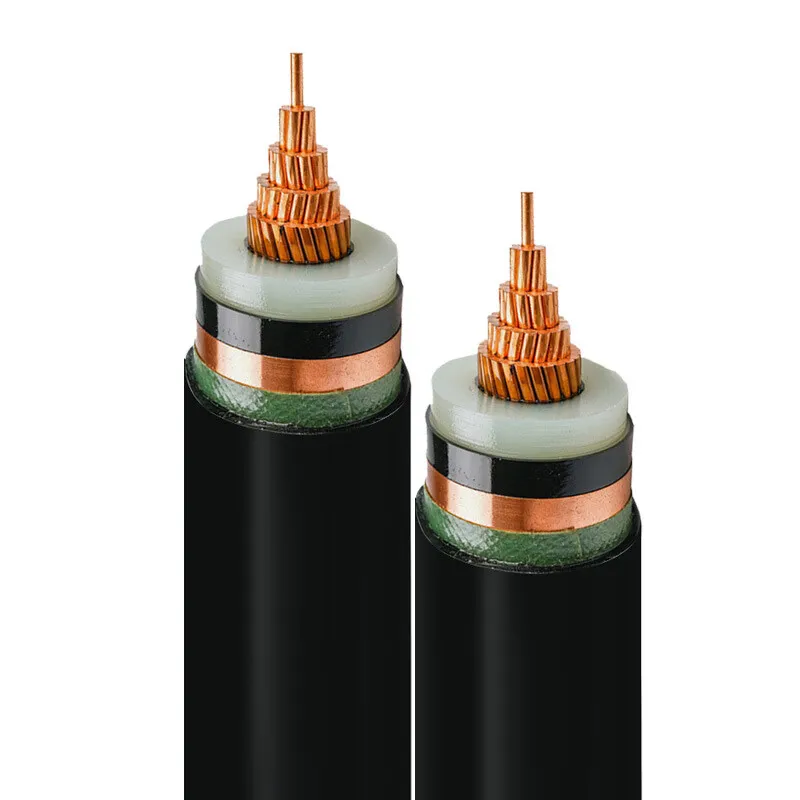
Table of Contents
1. Planning and Preparation
Effective planning is essential to ensure safe and efficient MV cable installation:
-
Site Survey: Conduct a detailed survey to assess soil conditions, groundwater levels, and obstacles (e.g., rocks, utilities). Identify corrosive soils or high-traffic areas requiring additional cable protection.
-
Cable Route Design: Plan the shortest, most accessible route, avoiding sharp bends (minimum bend radius typically 10–15 times cable diameter) and proximity to heat sources or other utilities.
-
Load and Voltage Drop Calculations: Calculate conductor size based on current load, cable length, and allowable voltage drop (typically <3% per IEC 60364) using standards like NEC or IEC tables.
-
Regulatory Compliance: Ensure compliance with standards such as IEC 60502-2, UL 1072, or local codes (e.g., BS 7671, NFPA 70) for cable specifications and installation practices.
-
Permits and Approvals: Obtain necessary permits for excavation, environmental compliance, and utility coordination to avoid delays.
-
Personnel Training: Engage certified electricians and contractors trained in MV cable handling and safety protocols, per IEC 60079-14 for hazardous areas if applicable.
-
Equipment Readiness: Ensure availability of specialized equipment, such as cable pulling winches, rollers, and trenching machines, calibrated for MV cable installation.
2. Cable Selection and Specifications
Selecting appropriate MV cables ensures performance and longevity:
-
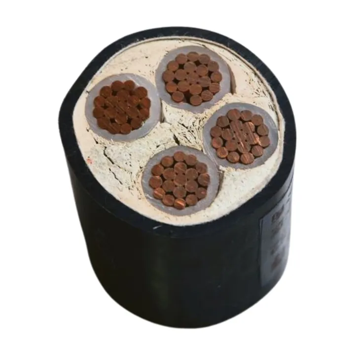
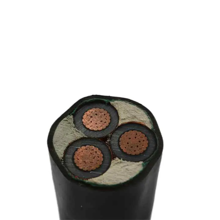
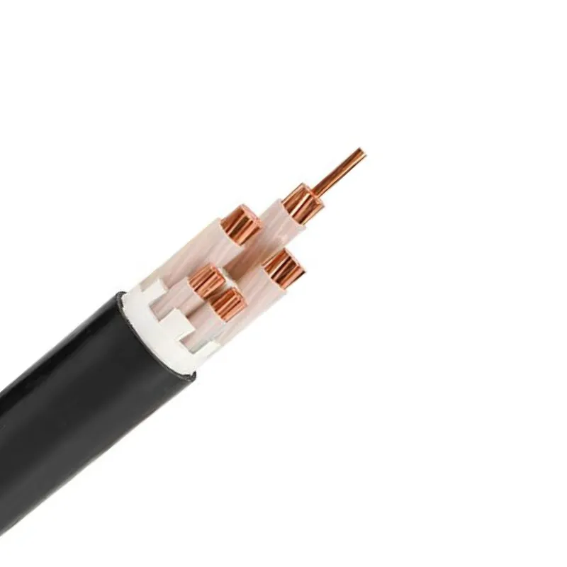
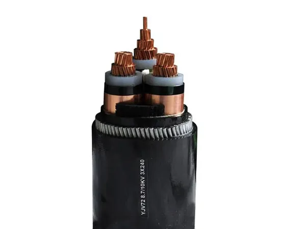
Conductor: Copper or aluminum, with stranded conductors (Class 2 per IEC 60228) for flexibility and high conductivity. Copper is preferred for higher efficiency; aluminum for cost savings.
-
Insulation: Cross-linked polyethylene (XLPE) for superior dielectric strength and thermal resistance (up to 90°C); ethylene propylene rubber (EPR) for enhanced flexibility in dynamic environments.
-
Sheathing: Polyethylene (PE) or low-smoke, zero-halogen (LSZH) for moisture resistance and fire safety in confined spaces.
-
Armoring: Steel wire armor (SWA) or steel tape armor (STA) for mechanical protection in direct burial or high-risk areas.
-
Shielding: Copper tape or wire shielding to reduce electromagnetic interference (EMI) and ensure fault current paths.
-
Voltage Rating: 6/10 kV, 8.7/15 kV, 12/20 kV, or 18/30 kV, based on project requirements.
-
Environmental Protection: Water-blocking tapes or compounds for IP67/68 ratings to prevent moisture ingress in underground or wet conditions.
-
Certifications: Compliance with IEC 60502-2, UL 1072, or EN 50575 (CPR classifications for fire performance).
3. Installation Best Practices
Proper installation techniques minimize risks and ensure cable integrity:
-
Trenching and Bedding:
-
Dig trenches to a depth of 0.8–1.2 m (per IEC 60364 or local codes), ensuring clearance from other utilities.
-
Use fine sand or sifted soil as bedding (100–150 mm thick) to cushion cables and prevent damage from rocks.
-
Place warning tapes or tiles above cables to alert future excavations.
-
Cable Pulling:
-
Use cable rollers and pulling lubricants to reduce friction, ensuring pulling tension does not exceed manufacturer limits (typically 50 N/mm² for copper).
-
Maintain minimum bend radius during pulling to avoid insulation or conductor damage.
-
Employ dynamometers to monitor pulling tension and prevent overstressing.
-
Direct Burial vs. Conduit:
-
For direct burial, use armored cables (SWA/STA) to protect against soil pressure and external damage.
-
For conduits or ducts, ensure smooth, non-abrasive interiors and adequate diameter (1.5 times cable diameter) to facilitate pulling and heat dissipation.
-
Sealing and Glanding: Use IP67/68-rated, heat-shrink or cold-shrink cable glands to prevent water ingress, ensuring compatibility with cable diameter and environmental conditions.
-
Grounding and Bonding: Connect cable shields and armoring to an equipotential grounding system to handle fault currents and prevent electrical hazards, per IEC 60364-5-54.
-
Jointing and Termination:
-
Use pre-molded or heat-shrink joints and terminations designed for MV applications, ensuring proper insulation and stress control.
-
Perform jointing in clean, dry conditions to avoid contamination, using trained personnel.
-
Segregation: Separate MV cables from low-voltage or communication cables by at least 150 mm to minimize EMI, per IEC 60079-14.
-
Protection Against Overheating: Ensure adequate spacing (1–2 cable diameters) in cable trays or ducts to allow heat dissipation, adhering to ampacity derating factors in IEC 60287.
4. Testing and Commissioning
Thorough testing ensures cable system reliability and safety:
-
Pre-Installation Testing: Inspect cables for physical damage and perform insulation resistance tests (using 5000 V DC megohmmeter) to verify integrity before laying.
-
Post-Installation Testing:
-
Insulation Resistance Test: Measure resistance (typically >100 MΩ) to detect insulation defects.
-
High-Voltage Test: Apply a test voltage (e.g., 2.5 times rated voltage for 15 minutes, per IEC 60502-2) to confirm dielectric strength.
-
Partial Discharge Test: Detect insulation weaknesses in joints and terminations, ensuring levels are below 10 pC, per IEC 60270.
-
Continuity Test: Verify conductor continuity and proper phase connections.
-
Commissioning: Gradually energize the system, monitoring for faults using protective relays and SCADA systems to ensure stable operation.
-
Documentation: Record test results, cable routes, and installation details for compliance and future reference.
5. Maintenance Guidelines
Regular maintenance ensures long-term performance and safety:
-
Periodic Inspections: Conduct annual visual inspections for signs of external damage, corrosion, or exposure, per IEC 60364-6.
-
Electrical Testing: Perform insulation resistance and partial discharge tests every 2–3 years to detect degradation.
-
Thermal Monitoring: Use infrared thermography to identify hotspots in joints or terminations, indicating potential faults.
-
Environmental Checks: Monitor soil conditions and groundwater levels to assess corrosion risks, applying protective coatings if necessary.
-
Repair Protocols: Replace damaged sections with compatible cables and joints, ensuring repairs meet original specifications.
-
Maintenance Records: Maintain detailed logs of inspections, tests, and repairs for regulatory compliance and troubleshooting.
6. Common Challenges and Solutions
|
Challenge
|
Solution
|
|
Moisture Ingress
|
Use water-blocking tapes/compounds and IP67/68-rated glands; ensure proper sealing at joints.
|
|
Mechanical Damage
|
Select armored cables (SWA/STA); use protective bedding and warning tapes in trenches.
|
|
Overheating
|
Ensure proper spacing and derating per IEC 60287; use thermal monitoring during operation.
|
|
EMI Interference
|
Employ shielded cables and segregate from low-voltage or communication cables.
|
|
Faulty Joints/Terminations
|
Use pre-molded or heat-shrink accessories; perform partial discharge tests post-installation.
|
|
Regulatory Non-Compliance
|
Verify certifications (IEC 60502-2, UL 1072); engage third-party inspectors for audits.
|
7. Conclusion
Laying medium voltage power cables (1 kV–35 kV) requires careful planning, precise installation, and rigorous testing to ensure safety, reliability, and compliance. By conducting thorough site surveys, selecting cables with appropriate insulation (XLPE/EPR), armoring, and shielding, and adhering to installation best practices such as proper trenching, sealing, and grounding, project managers can minimize risks and optimize performance. Regular maintenance and testing, including insulation resistance and partial discharge tests, ensure long-term reliability. By addressing common challenges like moisture ingress and mechanical damage with robust solutions, MV cable systems can support critical infrastructure in industrial, utility, and renewable energy applications effectively.

