Keep up to date with our latest company news and relevant industry knowledge.
Time: 2026-11-18 07:35:58 Source: Henan Province Jianyun Cable Co., Ltd.
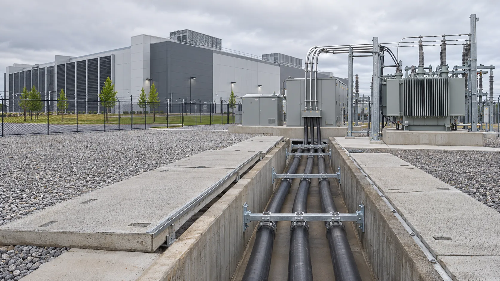
As data-center capacity expands, electrical infrastructure is becoming a central part of project planning.
The discussion often focuses on servers, cooling systems, UPS equipment, and backup generation. But before power reaches the data hall, it must move safely and reliably from the utility connection through substations, medium-voltage feeders, transformers, and distribution equipment.
For large data-center developments, medium-voltage cable is no longer a routine procurement item. It is part of the project’s capacity plan, redundancy strategy, construction schedule, and long-term expansion path.
Modern data centers require large, continuous electrical loads and very high availability.
As project capacity grows, low-voltage distribution alone is not sufficient for the main utility connection and campus-level power network. Medium-voltage systems are commonly used to bring power from the utility connection to on-site substations, main transformers, and major distribution points.
This means cable planning must begin early in the project.
A medium-voltage cable system for a data center may need to support:
Utility incoming feeders
Main substation connections
Medium-voltage ring networks
Transformer primary connections
Separate A and B power paths
Standby or alternate-feeder arrangements
Future building phases and capacity expansion
The cable must be selected as part of the complete electrical system—not only by conductor size or voltage class.
A typical large data-center power path includes several stages.
Power enters the site through a utility connection, often at medium voltage. It is transferred through incoming feeders to a main substation, then distributed to transformers that step voltage down for low-voltage switchgear, UPS systems, cooling equipment, and IT loads.
The medium-voltage section may include underground ducts, cable trenches, indoor switchgear rooms, outdoor substations, or a combination of these environments.
At every stage, the cable design must match the electrical and installation requirements.
Important considerations include:
Required system voltage
Short-circuit duty
Required ampacity
Route length and voltage drop
Installation method
Cable bending radius and pulling conditions
Termination and joint compatibility
Space for inspection, maintenance, and future expansion
A cable route that works for an initial phase may not be suitable for a larger future load if expansion is not considered early.
15 kV, 25 kV, and 35 kV cables are all used in distribution projects, but they are not interchangeable.
The required cable class must match the system voltage, equipment ratings, switchgear, terminations, and project specification.
Selecting a higher voltage cable without a complete system requirement can increase cable size, accessory cost, and installation complexity. Selecting a lower voltage class than required creates an unacceptable compatibility and reliability risk.
The project electrical design should always define the required voltage class before the cable RFQ is issued.
Both copper and aluminum conductors can be used for medium-voltage cable, depending on the project design.
Copper provides high conductivity in a smaller conductor size. Aluminum is lighter and may provide a cost-effective option where the system design allows a larger cross-section.
The decision should consider:
Required current capacity
Voltage drop
Short-circuit capability
Cable weight and pulling requirements
Termination compatibility
Available route space
Overall project budget
The correct choice is not simply the lowest material cost. It is the conductor that supports the complete electrical and installation design.
Single-core cable is often used in high-current applications, major substations, and certain duct-bank configurations.
Three-core cable may provide a compact installation solution for some medium-voltage distribution systems.
For data-center projects, the choice depends on current demand, installation layout, cable-tray space, duct-bank arrangement, termination design, and the preferred maintenance approach.
Where single-core AC cables are used, the complete design must also consider suitable non-magnetic accessories and correct cable arrangement.
Medium-voltage cable construction must suit the actual installation route.
A data-center campus may include underground duct banks, direct-burial sections, concrete cable trenches, tunnels, indoor substations, and outdoor equipment areas.
The RFQ should state whether the cable requires:
Armor for mechanical protection
Water-blocking features
A specific outer sheath material
Flame-retardant or low-smoke construction
Resistance to moisture, chemicals, UV exposure, or temperature variation
Specific pulling, bending, or installation requirements
Installation conditions can affect the cable construction, ampacity, accessories, and total project cost.
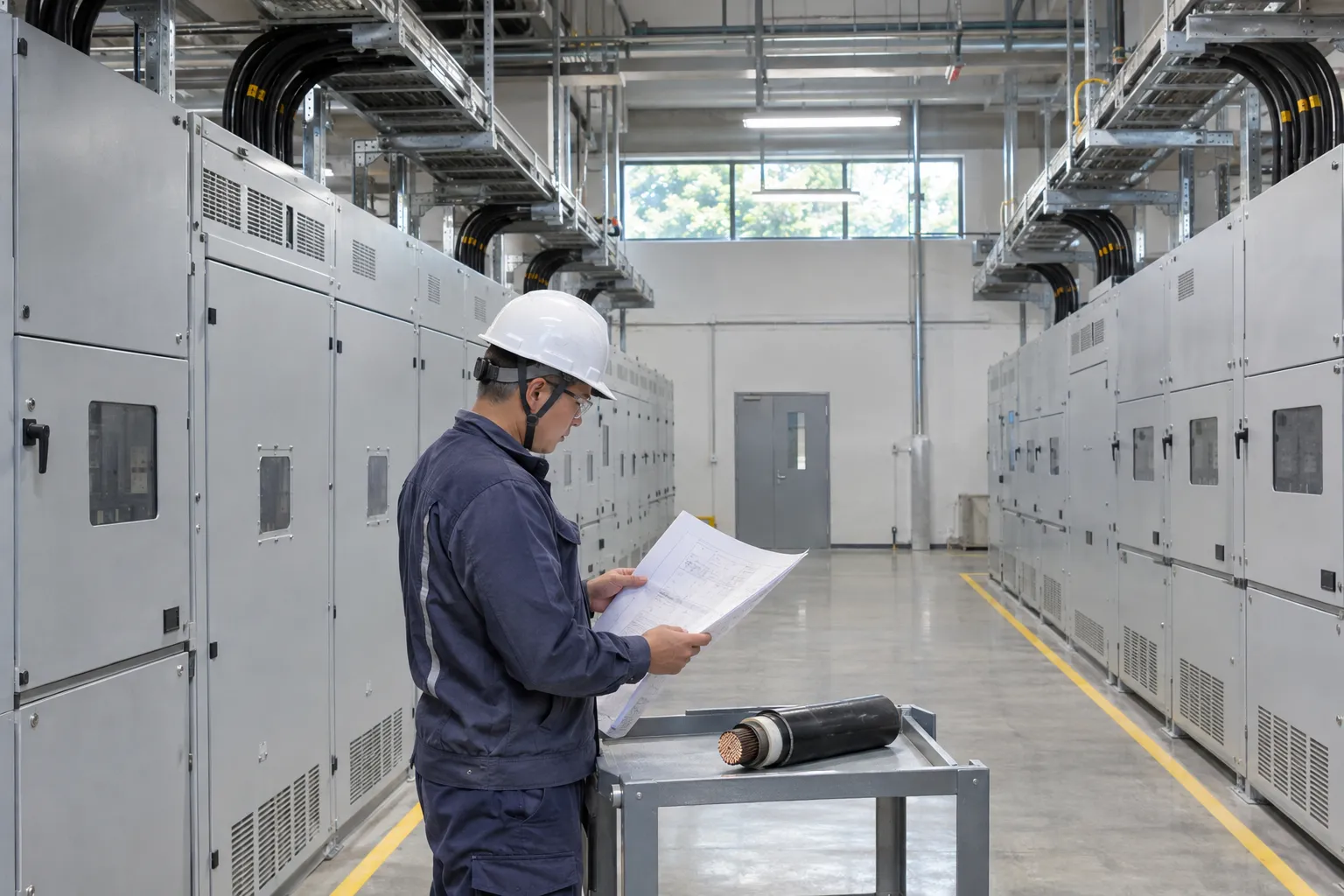
Redundancy is a defining feature of many data-center electrical systems.
A project may use separate A and B power paths, multiple transformers, alternative feeders, or phased capacity expansion. Each of these decisions affects the cable route and procurement plan.
For example, a project may require:
Two independent medium-voltage feeder routes
Physically separated cable paths
Spare ducts for future feeders
Additional cable capacity for expansion
Separate drum lengths for different installation areas
Clearly identified delivery sequences for phased construction
Cable quantities should not be calculated only from the shortest route to the transformer. The project team must also consider route separation, redundancy, spare capacity, joint locations, and installation losses.
Planning these details early reduces the risk of late design changes and site-level material shortages.
For large infrastructure projects, cable lead time should be considered during engineering—not only after the purchase order is issued.
Medium-voltage cable delivery depends on the final cable design, conductor material, insulation and screen construction, armor requirements, testing, drum lengths, packing, and destination.
The schedule may also be affected by the quantity of cable needed for multiple buildings, separate feeder routes, and project phases.
To reduce delays, confirm the following as early as possible:
Voltage class
Conductor material and cross-section
Single-core or three-core construction
Installation method
Cable standard and test requirements
Quantity and preferred drum length
Required delivery sequence
Destination and packing requirements
Accessory and termination requirements
A complete RFQ enables the supplier to provide a more accurate quotation and a more reliable delivery plan.
Before requesting a quotation, provide the following information:
Required voltage class
Required conductor material and cross-section
Single-core or three-core cable construction
System ampacity and short-circuit requirements
Installation method and route environment
Armor, sheath, screen, and water-blocking requirements
Applicable standard and testing requirements
Total quantity and preferred cable length per drum
Required delivery date and phased delivery schedule
Delivery location and export-packing requirements
Required terminations, joints, or compatible accessories
Future expansion or spare-feeder requirements
The more complete the project information, the easier it is to select a cable design that supports both current capacity and future growth.
Data-center growth is increasing the importance of medium-voltage power distribution.
The right cable solution depends on more than voltage class. It must support the project’s load requirement, redundancy plan, installation route, equipment compatibility, delivery schedule, and future expansion strategy.
Explore Jianyun Cable’s Medium Voltage Power Cable solutions for utility, industrial, renewable-energy, and critical-infrastructure projects.
For a project-specific recommendation, send your voltage class, conductor preference, installation method, quantity, delivery schedule, and destination through Jianyun Cable’s inquiry page.

