
Keep up to date with our latest company news and relevant industry knowledge.
Time: 2025-06-02 15:02:53 Source: Henan Province Jianyun Cable Co., Ltd.
Photovoltaic (PV) wire is a specialized cable used to interconnect solar modules, junction boxes, and inverters in photovoltaic systems. It features stranded tinned-copper conductors with cross-linked thermoset insulation and jacket—typically XLPE or XLPO—engineered for continuous exposure to UV, high temperatures (–40 °C to +90 °C), moisture, and ozone without degradation. PV wire is designed to meet strict performance requirements for flame resistance, weathering, and low-temperature flexibility. Variants include single-conductor, multi-conductor, USE-2, and TFFN, each serving different system sizes and installation contexts. Proper selection and installation ensure system longevity, efficiency, and safety over a 20–25 year service life.
Standard building or appliance wires degrade quickly under sustained sunlight, temperature extremes, or mechanical stress typical in rooftop or outdoor photovoltaic installations. PV wire was developed to address these challenges: its insulation and jacket materials resist UV, ozone, and temperature cycling, while its stranded tinned-copper conductors maintain conductivity without oxidation. This article explains PV wire’s construction, industry standards, common types, performance requirements, and best practices for installation and maintenance.
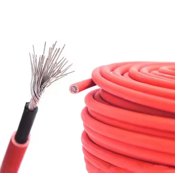
PV wire conductors are made of fine, stranded tinned-copper (often Class 2 uncoated or Class 5 tin-coated) to combine flexibility with corrosion resistance. The tin plating prevents copper oxidation under moisture and humidity, ensuring long-term reliability. Common conductor sizes range from 18 AWG through 4 AWG, depending on current requirements and run lengths.
PV wire uses cross-linked polyethylene (XLPE) or cross-linked polyolefin (XLPO) thermoset compounds for both insulation and outer jacket, providing superior resistance to UV radiation, ozone, and thermal aging. The insulation and jacket thickness exceed that of typical USE-2 wire by approximately 15 mils, adding mechanical protection against abrasion and impact. Jackets are often colored black or red for polarity identification and are formulated to pass vertical and horizontal flame tests.
PV wire must comply with UL 4703 (Photovoltaic Wire Standard) to certify its suitability for exposed rooftop or outdoor use. UL 4703 specifies tests for flame resistance (vertical and horizontal flame tests), weatherometer exposure (720 hours), and low-temperature flexibility (–40 °C). The National Electrical Code (NEC) Article 690 mandates UL 4703 compliance for PV wiring in the United States, ensuring safe installations for ungrounded arrays and transformerless inverters.
USE-2 wire, while rated for direct burial and 90 °C, lacks the thicker jacket and stringent flame tests required for exposed PV use; hence PV wire must be used where NEC Article 690 applies. Other applicable standards include IEC 62930 for international PV cable certification, ensuring UV resistance, thermal endurance (–40 °C to +90 °C), and mechanical durability for 20 years of outdoor service.
Single-conductor PV wire consists of one insulated tinned-copper conductor and is commonly used for module-to-module interconnections and string runs. These wires simplify rooftop runs and facilitate series/parallel wiring schemes. Single-conductor PV wire typically carries 600 Vdc to 1,500 Vdc system voltages and is available in colors (black, red) to denote positive and negative leads.
Multi-conductor PV cable bundles two or more insulated conductors within a single jacket, reducing clutter and installation time for systems requiring parallel runs or communication pairs. These assemblies may contain two, three, or four conductors, each individually insulated with XLPO, then jacketed together for mechanical protection. This simplifies conduit fill and makes cable management easier in combiner box to inverter wiring.
USE-2 wire is rated for 90 °C wet/dry and for direct burial, but its insulation is thinner than PV wire’s and has less UV resistance. It does not undergo the same flame testing as PV wire, making it unsuitable for exposed rooftop installations unless covered by conduit or proper raceways. PV wire is specifically tested for 720 hours in a weatherometer and –40 °C cold bending, whereas USE-2 undergoes only 300 hours and –25 °C cold tests.
TFFN (Thermoplastic Flexible Fixture Nylon) wire features a thermoplastic PVC insulation with a nylon jacket, offering flexibility and abrasion resistance. Although not always UL 4703 certified, TFFN is used for internal wiring within junction boxes, combiner boxes, and for short connector leads where high flexibility is required. Its temperature rating is generally –20 °C to +90 °C, making it suitable for fixture wiring but not for exposed runs without additional UV-resistant jacket.
PV wire must reliably operate over a 20–25 year service life under constant UV irradiation, thermal cycling, mechanical loading (wind, snow, foot traffic), and potential abrasion from installation surfaces. UV-stabilized XLPO/XLPE compounds prevent degradation, while ozone-resistant jackets avoid cracking in open-air environments. Tinned-copper conductors maintain low electrical resistance and avoid oxidation at terminal points, ensuring minimal power losses over time.
Mechanical tests include impact resistance, abrasion resistance, and tensile strength to withstand installation stresses and rooftop foot traffic. PV wire also undergoes flame tests (vertical and horizontal) to limit fire propagation in array installations, critical for rooftop fire safety and code compliance.
Electrical tests verify continuous ampacity at high dc voltages (600 V to 1,500 V) and insulation resistance at elevated temperatures. Proper conductor sizing (e.g., 10 AWG for typical 30 A string, 12 AWG for 20 A applications) ensures voltage drop remains within acceptable limits (< 2%) for system efficiency.
PV wire is used throughout the balance-of-system (BOS) wiring of solar PV installations:
Proper installation of PV wire is crucial for safety and longevity:
Photovoltaic (PV) wire is a critical component of solar energy systems, engineered with tinned-copper conductors and UV-resistant thermoset insulation/jackets to withstand prolonged outdoor exposure, temperature extremes, UV radiation, and mechanical stresses. Compliance with relevant standards ensures safety, reliability, and longevity under harsh conditions. Understanding conductor sizes, insulation materials, and performance tests enables designers and installers to select appropriate PV wire types—single-conductor, multi-conductor, USE-2, or TFFN—and implement best practices in routing, securing, and terminating cables. Proper selection and installation maximize system efficiency, minimize maintenance, and ensure safe operation of photovoltaic installations over their useful life.