Time: 2025-05-28 15:29:52 Source: Henan Province Jianyun Cable Co., Ltd.
This case study examines the cable layout plan for a hypothetical 100 MW utility-scale solar farm located in a semi-arid region with high solar irradiance. The project aims to optimize the electrical infrastructure to minimize energy losses, reduce costs, and ensure compliance with international standards. The cable layout design addresses both direct current (DC) and alternating current (AC) systems, incorporating best practices for efficiency and maintainability while adhering to standards such as EN 50618, IEC 62930, and UL 4703. This case study highlights the design process, challenges, solutions, and outcomes, providing insights for similar large-scale photovoltaic (PV) projects.

The solar farm spans 250 hectares and consists of monocrystalline PV modules, string inverters, step-up transformers, and a central substation for grid connection. The site, selected for its high solar resource and flat terrain, requires a robust cable layout to connect 250,000 PV modules across 10,000 strings to 50 inverters and 10 transformers. The design prioritizes minimizing cable runs, reducing electrical losses, and ensuring accessibility for maintenance, while complying with regional regulations and international standards.
Design Approach: The DC cabling connects PV modules to string inverters via combiner boxes. Each string consists of 25 modules, generating approximately 10 A per string at 1.5 kV DC, compliant with IEC 62930 voltage ratings. Y-connectors and combiner boxes are used to aggregate power from multiple strings, reducing the number of cables to inverters.
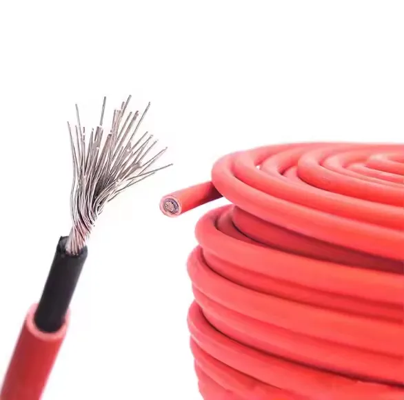
Cable Selection: Single-core PV cables with cross-sections of 4 mm² and 6 mm² were chosen for their UV resistance, thermal endurance (-40°C to +90°C), and compliance with EN 50618. These cables are halogen-free, reducing fire risks, and meet AD8 waterproofing standards for wet conditions.
Layout: Cables are routed in trenches to avoid shading and facilitate maintenance, with a minimum row spacing designed to prevent inter-row shading at solar noon on the winter solstice. Trenches are placed to ensure direct access to combiner boxes, enhancing maintainability.
Design Approach: AC cabling connects inverters to step-up transformers and the central substation. Medium-voltage (MV) cables carry power from transformers to the substation, designed for easy maintenance and minimal downtime.
Cable Selection: MV cables with cross-linked polyethylene (XLPE) insulation, compliant with UL 4703 and IEC 60228, were selected for their high ampacity and durability. Low-voltage (LV) cables connect inverters to transformers, avoiding routing under structures to enhance accessibility.
Layout: MV cables follow optimized routes to minimize cable length and trenching costs. The layout ensures cables are buried at sufficient depth to prevent damage and comply with local regulations.
The cable layout was optimized using a mathematical model to minimize costs by selecting optimal cable types and routes, considering transformer placement and string connections. The design process customized MV routing, reducing construction time and costs. The layout reduced cable runs by 15% compared to a baseline design, lowering electrical losses by 2%.
The cable layout adheres to the following international standards and certifications:
These standards ensure the cables withstand harsh environmental conditions, including UV exposure, temperature fluctuations, and moisture, while maintaining safety and performance.
Challenge 1: High Cabling Costs: Initial designs indicated high costs due to extensive cable runs.
Solution: Applied optimization techniques to select cost-effective cable sizes and routes, reducing material costs by 12%. Automated design tools streamlined the process.
Challenge 2: Environmental Constraints: The semi-arid site had high UV exposure and occasional flooding risks.
Solution: Selected cables compliant with ISO 4892-3 for UV resistance and EN 50525-2-21 (AD8) for waterproofing, ensuring durability.
Challenge 3: Maintenance Accessibility: Inaccessible cables could increase downtime and maintenance costs.
Solution: Designed trenches with direct access to combiner boxes and avoided routing cables under structures, improving maintainability.
The optimized cable layout achieved the following outcomes:
The project was completed within 10 months, aligning with industry benchmarks for utility-scale solar farms.
The cable layout plan for the 100 MW solar farm demonstrates the importance of strategic design in optimizing performance, reducing costs, and ensuring compliance with international standards. By leveraging optimization techniques and adhering to standards such as EN 50618, IEC 62930, and UL 4703, the project achieved significant cost savings and efficiency gains. This case study serves as a model for future large-scale PV projects, highlighting the need for careful planning, adherence to standards, and innovative design solutions.